Arduino: Project: Photoresistor to shutdown a computer, FlashlightToggle

The big idea of this project is to find alternative ways to shutdown / start up computers. I’ve already thought about clap-on, clap off toggle, but the sensor I was trying it with was bad. It didn’t give much or any changes in readings when sound was short. When sound was continious it gave little changes.

So to this project. The FlashlightToggle works like this: blink a flashlight to the photoresistor 5 times. Then python-serial reads the value serial is giving and runs shutdown command, computer shuts down. If you only flash light one to four times, nothing happens and if you wait for 20 seconds of the first flashing, it resets.

Testing arduino:

ALWAYS before starting a new project, one must test arduino with hello world (blink). Check my earlier blog posts for this. Never skip it.

Installing Python and pySerial

To command line in Ubuntu 12.04:

sudo apt-get update
sudo apt-get install python
sudo apt-get install python-serial

Testing:

So to test out, I’m going to insert my arduino to testing machine, type:

sudo python

and write down:

import serial
ser = serial.Serial('/dev/ttyACM0', 9600)
while True:
   print ser.readline()

then after last line is written, unix command line starts printing arduino serial monitor

Example image from this project:

commandline

Tools and components:

Components:

Arduino UNO 3.0 (basicly any Arduino should fit)

Photoresistor

USB-cable

5x 220 Ohm resistors

1x 10k Ohm resistor

several jumper wires

Sketch:

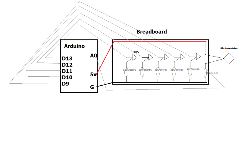
Here is beautiful sketch made by me. Simply connect leds to digital ports and ground through 220 ohms. Photoresistor need to have 10k ohm to ground, and between photoresistor and 10k you wire jumperwire to analog port. Also you have to give it 5v power.

arduino_breadboard

Tools:

I used Arduino IDE for coding and to insert my codes to Arduino.

Arduino C++ code:

const int gled1 = 13;
const int yled1 = 12;
const int yled2 = 11;
const int rled1 = 10;
const int rled2 = 9;
const int lightsensor = 0;

double sensorreading = 0.0;
int rbit2 = 0;
int rbit1 = 0;
int ybit2 = 0;
int ybit1 = 0;
int gbit1 = 0;
int time;
int x = 0;
int target = 0;

void setup() {
  Serial.begin(9600);  
  Serial.println("Serial started:");
  pinMode(gled1, OUTPUT);
  pinMode(yled1, OUTPUT); 
  pinMode(yled2, OUTPUT); 
  pinMode(rled1, OUTPUT); 
  pinMode(rled2, OUTPUT);  
}

void loop() {
  sensorreading = analogRead(lightsensor) / 1023.0;
  Serial.println(sensorreading);
  if(sensorreading > 0.88 && rbit2 == 0){
    digitalWrite(rled2, HIGH);
    delay(500);
    rbit2 = 1;
  }
  sensorreading = 0.00;
  sensorreading = analogRead(lightsensor) / 1023.0;
  if(sensorreading > 0.88 && digitalRead(rled2) && rbit1 == 0){
    digitalWrite(rled1, HIGH);
    delay(500);
    rbit1 = 1;
  }
  sensorreading = 0.00;
  sensorreading = analogRead(lightsensor) / 1023.0;
  if(sensorreading > 0.88 && digitalRead(rled1) && ybit2 == 0){
    digitalWrite(yled2, HIGH);
    delay(500);
    ybit2 = 1;
  }
  sensorreading = 0.00;
  sensorreading = analogRead(lightsensor) / 1023.0;
  if(sensorreading > 0.88 && digitalRead(yled2) && ybit1 == 0){
    digitalWrite(yled1, HIGH);
    delay(500);
    ybit1 = 1;
  }
  sensorreading = 0.00;
  sensorreading = analogRead(lightsensor) / 1023.0;
  if(sensorreading > 0.88 && digitalRead(yled1) && gbit1 == 0){
    digitalWrite(gled1, HIGH);
    delay(500);
    gbit1 == 1;
    lightshow();
  }
  delay(100);
  wait();
}
void wait(){
    time = millis()/1000;
    while(x == 0){
      if(rbit1 == 1 || rbit2 == 1 || ybit1 == 1 || ybit2 == 1 || gbit1 == 1){ 
        target = time + 20;
        x++;
      }
      x++;
    }
    if(time >= target){
     digitalWrite(gled1,LOW);
     digitalWrite(yled1,LOW);
     digitalWrite(yled2,LOW); 
     digitalWrite(rled2,LOW); 
     digitalWrite(rled1,LOW);
     rbit1 = 0;
     rbit2 = 0;
     ybit1 = 0;
     ybit2 = 0;
     gbit1 = 0;
     x=0; 
    }
}
void lightshow(){
     digitalWrite(gled1,HIGH);
     delay(50);
     digitalWrite(yled2,HIGH);
     delay(50);
     digitalWrite(yled1,HIGH);
     delay(50);
     digitalWrite(gled1,LOW);
     digitalWrite(rled2,HIGH);
     delay(50);
     digitalWrite(rled1,HIGH);
     digitalWrite(yled2,LOW);
     digitalWrite(gled1,HIGH);
     delay(50);
     digitalWrite(yled2,HIGH);
     delay(50);
     digitalWrite(yled1,HIGH);
     delay(50);
     digitalWrite(gled1,LOW);
     digitalWrite(rled2,HIGH);
     delay(50);
     digitalWrite(rled1,HIGH);
     digitalWrite(yled2,LOW);
     digitalWrite(gled1,LOW);
     digitalWrite(rled2,HIGH);
     delay(50);
     digitalWrite(rled1,HIGH);
     digitalWrite(yled2,LOW);
     delay(50);
     digitalWrite(gled1,LOW);
     digitalWrite(yled1,LOW);
     digitalWrite(yled2,LOW); 
     digitalWrite(rled2,LOW); 
     digitalWrite(rled1,LOW);
     rbit1 = 0;
     rbit2 = 0;
     ybit1 = 0;
     ybit2 = 0;
     gbit1 = 0;
     x=0;
     Serial.println("SHUTDOWN");
     delay(1000); 
   }

Python code:

import subprocess
import serial

ser = serial.Serial('/dev/ttyACM0', 9600, timeout=1)
while True:
        print ser.readline()
        line = ser.readline().decode('utf-8')[:-2]
        if line == 'SHUTDOWN':
                subprocess.call(["sudo", "shutdown","-h", "now"])

Just save this python code to lets say like shutdown-arduino.py, then run it into screen with

sudo screen python shutdown-arduino.py

and leave screen running with CTRL+A and CTLR+D

Now when flashlight hits the sensor 5 times, computer shuts down

Results in video (sorry about the wibbily wobbilyness, cameraman was little bit tired):

Info:

Computer:

P8-P67 Rev 3.0 motherboard, AMD 6970 HD 2gb grapich card, Intel I5-2500k 6mb cache 4,5 ghz processor, 8gb 1950mhz RAM, and other important components.

Operating System:

Windows 7 64-bit Professional, Service Pack 1

Testcomputer: Old laptop, running on Ubuntu 12.04

Resources:

Arduino: Serial monitor basics

Writing to serial monitor:

void setup() {                
  Serial.begin(9600);
  Serial.println("This will be only shown at the start");
}
void loop() {
  Serial.println("This will be looping with 1 sec interval");
  delay(1000);
}

Reading sensor values in serial monitor (from my earlier project, TMP sensor):

void setup() {
  Serial.begin(9600);
}

void loop() {
  int sensorValue = analogRead(A0);
  float volt = (sensorValue/1020.0) * 5.0; //Volts
  float tempC = (volt -0.5) * 100; //Celcius
  Serial.println(tempC); //this part is sending the temperature in celcius to serial monitor
  delay(1000);
}

Sending text to serial monitor and printing it out:

char serialmsg = ' ';

void setup() {                
  Serial.begin(9600);
  Serial.println("Serial started");
}

void loop() {
  if (Serial.available()>0) {
    serialmsg = Serial.read();
    Serial.print(serialmsg);
  }
  delay(100);
}

Computer:

P8-P67 Rev 3.0 motherboard, AMD 6970 HD 2gb grapich card, Intel I5-2500k 6mb cache 4,5 ghz processor, 8gb 1950mhz RAM, and other important components.

Operating System:

Windows 7 64-bit Professional, Service Pack 1

Resources:

Arduino: Project ideas

In this blog post I will list several project ideas that came up to my mind. After listing them, I will eliminate some of them. Then I’ll give a closer look to 3 of ideas and eliminate them, until I have only one idea.

That one idea will become my project to the course Building a Prototype, in HAAGA-HELIA.

Idealist

  • “Does the litter box smell?” – gas sensor to check how much gasses there are in the litter box. If too much, then it probably smells. Perhaps e-mail alert?
  • “Clap on your PC” – clapper to turn on or off your computer
  • Some other clapping / sound things, like press space bar (to pause / continue  movies)
  • Make lights stay at certain level
  • LED Cube ( for fun )
  • Self balancing 1 wheeled skateboard. I’ve seen some of these in the internet, but it would be so fun to build one.
  • Self adjusting mirror, adjusts by the position of the looker
  • “Nyt vesi päälle stna” – toggle waterboiler on through mobile app
  • “Angry neighbour” – Desibel meter, whines when party goes too loud. Automatically lowers music level

Elimination

I decided to pick up the cat poop smellie thingie, clap on your pc and angry neighbour. All of these could be in use in my own house.

“Does the litter box smell?”

Parts needed: Gas sensor and way to send email. Perhaps begin with just a led light.

“Clap on your PC”

Parts needed: Sound sensor. For testing purposes, old motherboard to contact directly 5v power from Arduino.

“Angry neighbour”

I think this could be easily done by servo motor and sound desibel meter. Servo motor turning the volume knob and desibel meter sensing how much noise we do.

Choise

After thinking about all these, I decided to start project “Clap on your PC”. This is because I usually leave my computer on (or fall a sleep in my bed whilst watching Netflix), but my electric bill is too much and it would be easy way to shut the computer down.

Resources:

Arduino: Gladiator killer thumb

Output with servo motor, pietzo and 2 leds. Idea is that when you change the position of potentiometer, sound begins and led lights up. If thumb goes up, green light turns on, if thumb goes down red light goes on. Sound also differs between up and down.

Tools and components:

Components:

Arduino UNO 3.0 (basicly any Arduino fits)

Potentiometer

Pietzo

2 leds, red and green

Servo motor

1 resistor 1k OHM

USB-cable

several jumper wires

Tools:

I used Arduino IDE for coding and to insert my codes to arduino.

Code using basic librarys

Servo.h and pitches.h (pietzo):

#include <Servo.h> 
#include <pitches.h>

Servo myservo;
int led1 = 10;
int led2 = 11;
int soundPin = 9;

void setup() {
  Serial.begin(9600);
  myservo.attach(13); 
  pinMode(led1, OUTPUT);
  pinMode(led2, OUTPUT);
}

void loop() {
  int potentiometervalue = analogRead(A0);
  potentiometervalue = map(potentiometervalue, 0, 1023, 0, 180);
  Serial.println(potentiometervalue);
  delay(10);
  myservo.write(potentiometervalue);
  delay(15);
  if(potentiometervalue < 30 ){
    digitalWrite(led1, HIGH);
    tone(soundPin, 440, 10);

  } 
  else{
    digitalWrite(led1,LOW);
  }
  if(potentiometervalue > 150){
    digitalWrite(led2, HIGH);
    tone(soundPin, 880, 10);
  } 
  else{
    digitalWrite(led2,LOW);
  }

}

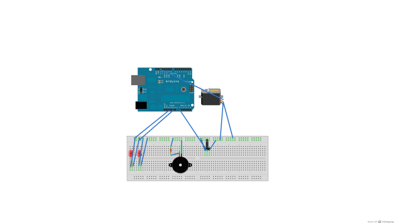
Cabling of breadboard + Arduino:

Untitled Sketch_bb

Video of the result:

Testing servo manual configuration

Here is just a small testing about servos manual configuration. We had minimum value of about 500, mid value 1450 and high value 2400. Code is from Tero Karvinen Book, Make Arduino Bots and Gadgets. More from teroterokarvinen.com.

int servoPin = 13;

void setup() {
  Serial.begin(9600);
  pinMode(servoPin, OUTPUT);
}
void pulseServo(int servoPin, int pulseLenUs)     
{
  digitalWrite(servoPin, HIGH);
  delayMicroseconds(pulseLenUs);
  digitalWrite(servoPin, LOW);
  delay (50);
}

void loop() {
  for (int i = 1; i<=3000; i=i+2){
    pulseServo(servoPin, i);
    Serial.println(i);
  }

}

Info:

Computer:

Lenovo ThinkPad Twist

Operating System:

Windows 7 64-bit Professional, Service Pack 1

Resources:

Arduino: LCD Temperature meter (TMP 36-sensor)

Temperature meter with TMP 36 sensor, prints the results to LCD screen.

Tools and components:

Components:

Arduino UNO 3.0 (basicly any Arduino fits)

Potentiometer (to change LCD screen text brightness)

TMP 36-sensor (temperature sensor) https://www.sparkfun.com/products/10988

USB-cable

LCD display (http://www.ebay.com/itm/1pcs-1602-16×2-HD44780-Character-LCD-Display-Module-LCM-blue-blacklight-New-/251049844026)

several jumper wires

Tools:

I used Arduino IDE for coding and to insert my codes to arduino.

Step 1, getting temperature sensor working

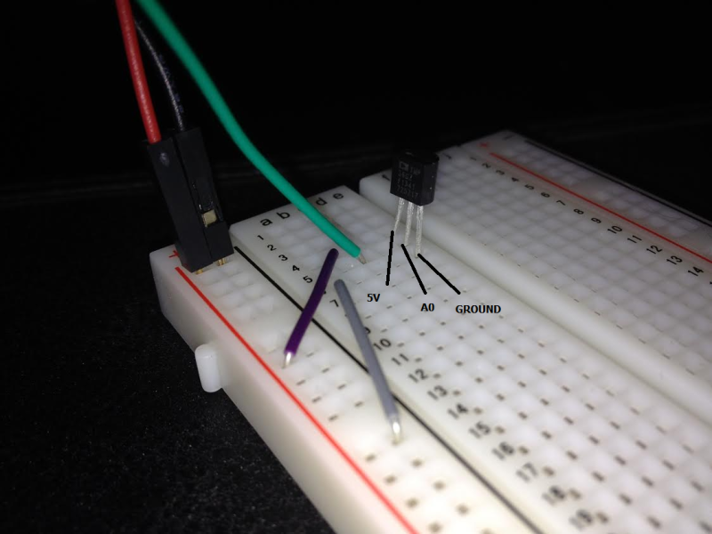
temp_wiring

Here is the cabling of temperature sensor. It is sort of a potentiometer, so it doesn’t need any resistors.

Code to read values it is giving:

void setup() {
  Serial.begin(9600);
}

void loop() {
  int sensorValue = analogRead(A0);
  float volt = (sensorValue/1020.0) * 5.0; //Volts
  float tempC = (volt -0.5) * 100; //Celcius
  Serial.println(tempC);
  delay(1000);
}


Step 2, printing to LCD screen

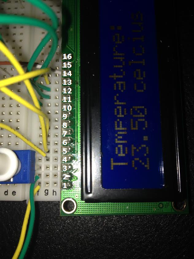
Wiring from LCD to Arduino goes like this:
1 = GND
2 = 5v+
3 = center of potentiometer (potentiometer leg 1 and 3 goes to 5v and ground)
4 Pin = 12 Arduino.
5 = GND
6 Pin = 11 Arduino
11 Pin = 5 Arduino
12 Pin = 4 Arduino
13 Pin = 3 Arduino
14 Pin = 2 Arduino
15 = 5v+ (220 ohm resistance)
16 = Gnd

lcd

In the code, you can see I have variable 4.9 (volt amount). You need to check how many volts are running to your sensor to get more precise amount.

Code:

#include <LiquidCrystal.h>
LiquidCrystal lcd(12, 11, 5, 4, 3, 2);  

void setup() {
  Serial.begin(9600);
  lcd.begin(16, 2); //initialize rows in lcd screen
  
}

void loop() {
  int sensorValue = analogRead(A0);
  float volt = (sensorValue/1020.0) * 4.9; //Volts
  float tempC = (volt -0.5) * 100; //Celcius
  Serial.println(tempC);
  lcd.setCursor(0, 0);
  lcd.print("Temperature:");
  lcd.setCursor(0, 1);
  lcd.print(tempC);
  lcd.print(" celcius");
  delay(3000);
}


Results, code and cabling

Here is result in video:

Info:

Computer:

P8-P67 Rev 3.0 motherboard, AMD 6970 HD 2gb grapich card, Intel I5-2500k 6mb cache 4,5 ghz processor, 8gb 1950mhz RAM, and other important components.

Operating System:

Windows 7 64-bit Professional, Service Pack 1

Resources:

Arduino: Clap on – clap off -LED light

Second little project in the course Building a prototype was to use any sensor and see what data it can give us. Next was to use this data to make something happen.

My project was to use sound level sensor and I decided to make it light up a led when clapped once and after that clapping once again would shut it down.

First off, always start with Hello World (Blink) just to check that your Arduino is working. Then we can start.

Tools and components:

Components:

Arduino UNO 3.0 (basicly any Arduino fits)

USB-cable

1 red led

several jumper wires

Sound-level sensor

The sound level sensor has a potentiometer to change the sensitivity of the sensor. I adjusted it to be highest available and I’m reading the digital input. If input gives me any number (it is giving nills and ones) then clapper activates. This is because it is not that good of a sensor and it needs relatively hard claps to give a digital reading. In the other hand the analog readings are constant and without any delay not that reasonable. (It is giving 530-550 all the time, whether it is receiving a loud or silent sound)

Tools:

I used Arduino IDE for coding and to insert my codes to arduino.

Results, code and cabling

Here is result in video:

Here is the code:

    int digPin = 2;       
    int greencar = 13;                                 
    void setup(){
      Serial.begin(9600);
      pinMode(digPin, INPUT);
      pinMode(greencar, OUTPUT); 
    }
    void loop(){
      if (digitalRead(digPin)){
        digitalWrite(greencar, HIGH);
        Serial.print("Sensor Value: ");
        Serial.println(digitalRead(digPin));
        delay(1000);
      }
      if (digitalRead(greencar)){
        if (digitalRead(digPin)){
          digitalWrite(greencar, LOW);

          delay(1000);
        }
      }
    }

And here is the cabling:

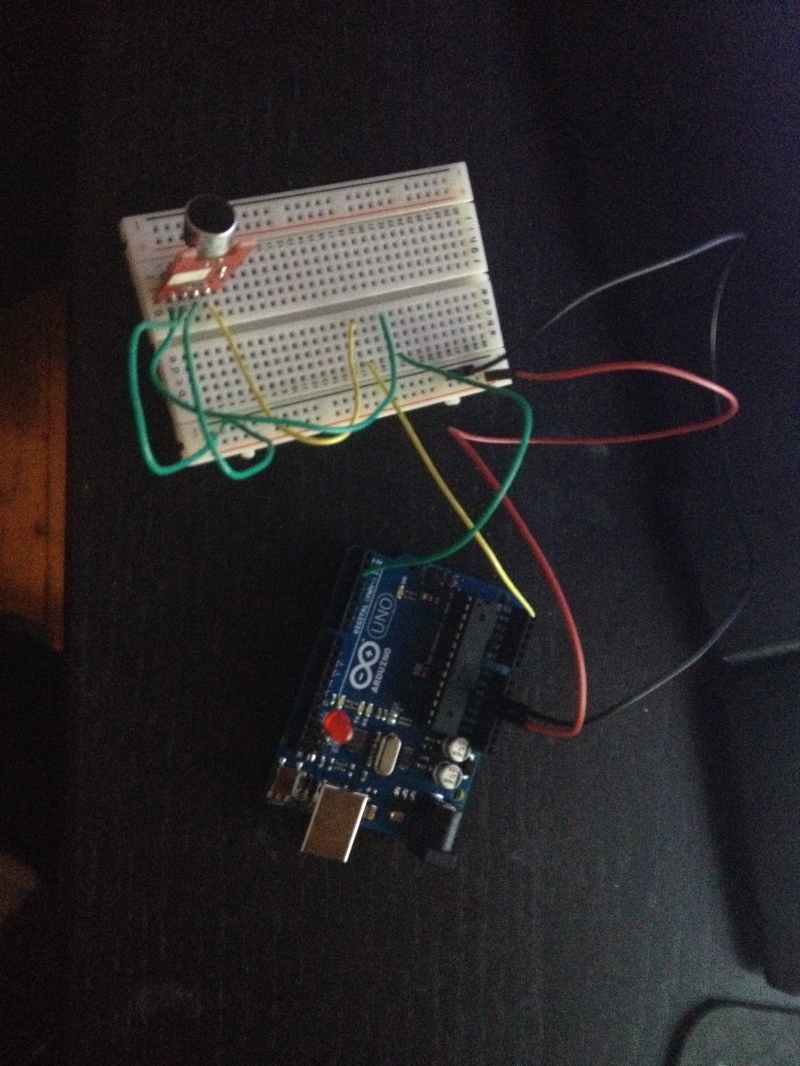
Sound sensor has 4 pins, from top to bottom: Analog output, ground, 5v+, Digital output. Those are put in to the given places in arduino (top to bottom: Analog 5, Ground, 5v+, Digital 2) and then there is the led in 13 and ground.

photo

Info:

Computer:

P8-P67 Rev 3.0 motherboard, AMD 6970 HD 2gb grapich card, Intel I5-2500k 6mb cache 4,5 ghz processor, 8gb 1950mhz RAM, and other important components.

Operating System:

Windows 7 64-bit Professional, Service Pack 1

Resources:

Arduino: Traffic ligths

I’m starting a new course in HAAGA-HELIA called Building a prototype (Prototyypin rakentaminen). I will blog every homework and all projects I do to my blog. First assignment was to build any little setup with LED ligths and some logic in Arduino. I decided to build traffic ligths. There are separate lights for cars and pedestrians.

Tools and components:

Components:

Arduino UNO 3.0 (basicly any Arduino fits)

USB-cable

2 green leds

2 red leds

1 yellow led

several jumper wires (I used 12)

5 resistors (220 Ω)

Tools:

I used Arduino IDE for coding and to insert my codes to arduino.

For sketch of the breadboard / arduino cabling, I used Fritzing.

Using the tools:

Arduino IDE:

1. Install Arduino IDE. I’m using Windows 64-bit OS, so it was basicly next next next finish installation.

2. Open Arduino IDE.

3. Open up any example (I prefer Blink, or as you may call it, Hello World) to test that your Arduino works.

4. Plug arduino in and press Upload button on the top of the software.

If it doesn’t work, try changing Serial Port from Tools / Serial Port.

Fritzing (optional):

It is adviced to have atleast hand written sketch of your setup. I’m using Fritzing for this.

1. Install, again next next finish.

2. Open up

3. Basicly drag and drop, really easy to use.

4. When board sketch is ready, export image as PNG.

Results, code and cabling

Here is result in video:

Here is the code:

int redcar = 11;
int yellowcar = 12;
int greencar = 13;
int greenped = 10;
int redped = 9;

void setup() {                
  pinMode(redcar, OUTPUT);  
  pinMode(yellowcar, OUTPUT);  
  pinMode(greencar, OUTPUT); 
  pinMode(greenped, OUTPUT); 
  pinMode(redped, OUTPUT);  
}

void loop() {
  digitalWrite(redcar, HIGH);
  digitalWrite(greenped, HIGH);
  delay(10000);
  digitalWrite(yellowcar, HIGH);
  digitalWrite(greenped, LOW);
  digitalWrite(redped, HIGH);
  delay(2000);
  digitalWrite(yellowcar, LOW);
  digitalWrite(redcar, LOW);
  digitalWrite(greencar, HIGH);
  delay(10000);
  digitalWrite(greencar, LOW);
  digitalWrite(yellowcar, HIGH);
  delay(2000);
  digitalWrite(yellowcar, LOW);
  digitalWrite(redped, LOW);

}

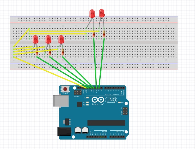
And here is the cabling (Fritzing had only red leds, or atleast I didn’t find any other colors :D):

liikennevalot_board

Info:

Computer:

P8-P67 Rev 3.0 motherboard, AMD 6970 HD 2gb grapich card, Intel I5-2500k 6mb cache 4,5 ghz processor, 8gb 1950mhz RAM, and other important components.

Operating System:

Windows 7 64-bit Professional, Service Pack 1

Resources: